




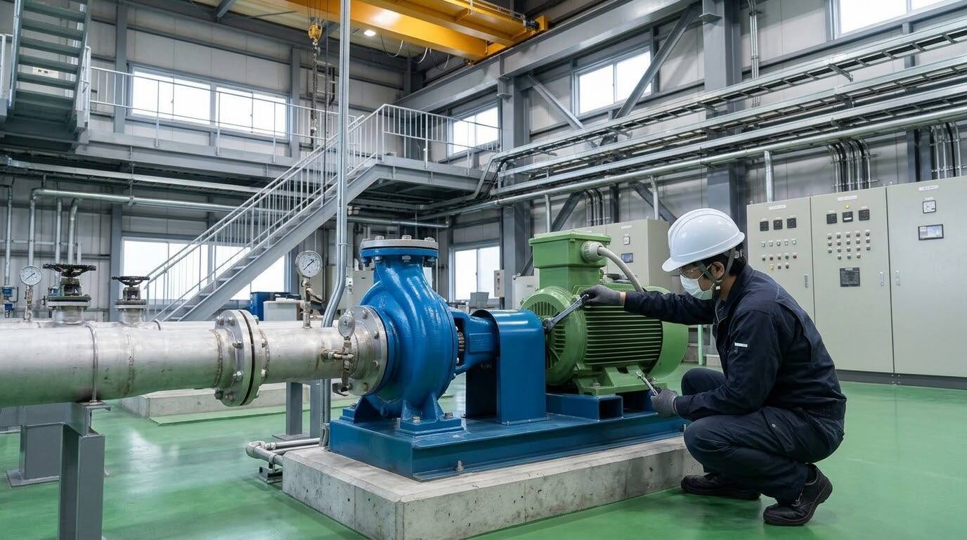
Predictive maintenance through vibration monitoring is highly effective for the stable operation of centrifugal pumps. Continuously acquiring vibration data provides early clues to internal equipment changes, component wear, and alignment deviations that are difficult for humans to notice. However, vibration data is just "one indicator of equipment condition." Data alone cannot definitively determine all causes of abnormalities; highly accurate diagnosis is achieved by combining it with on-site abnormal noises, temperatures, and operating conditions. This article provides a practical diagnostic guide for centrifugal pumps using conanair, explaining everything from sensor measurement positions to how to read the data.
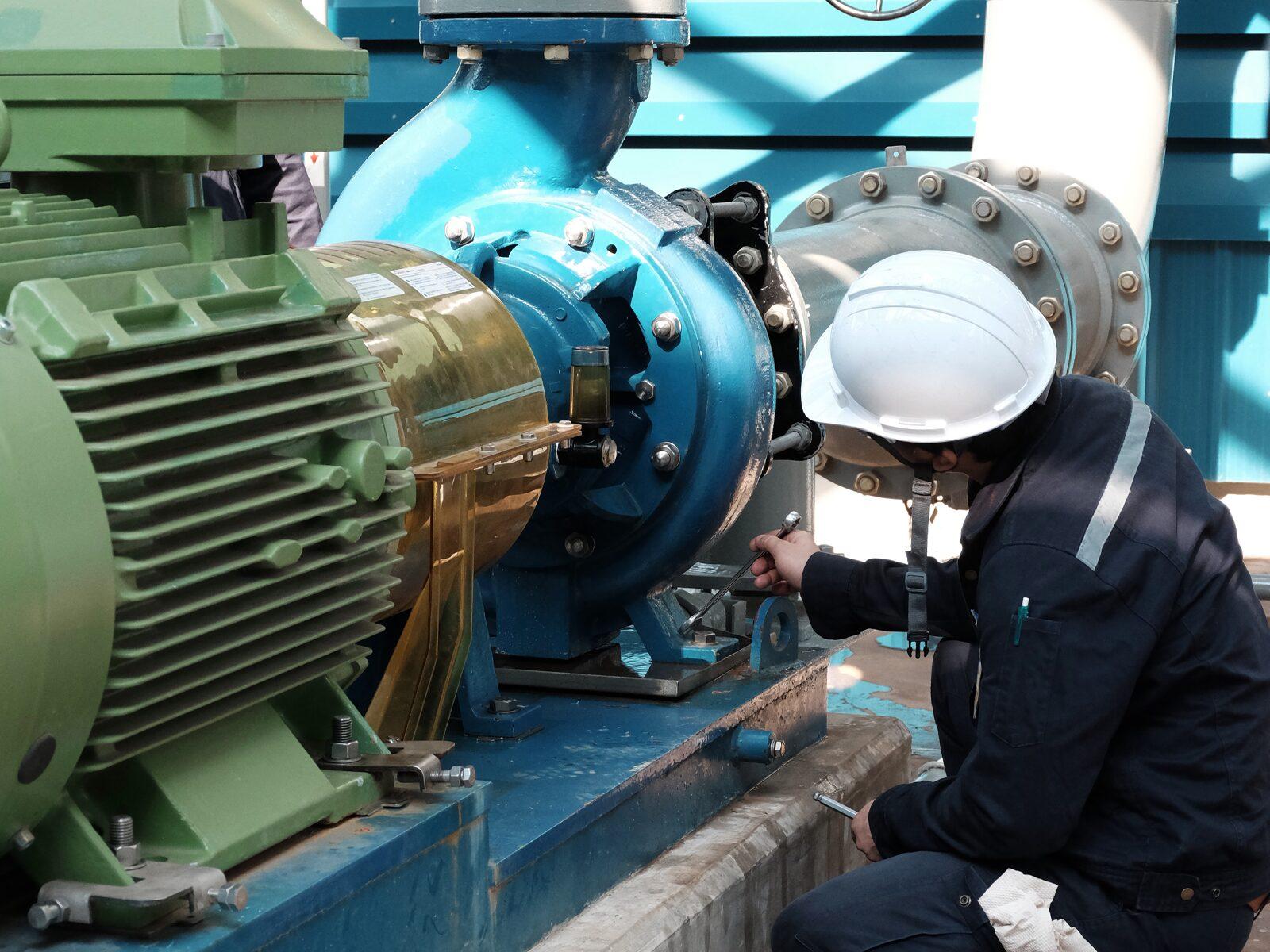
Where to install a vibration sensor depends on "what abnormality you want to detect." The basic rule is to choose the location where the target vibration is transmitted most easily.
To capture abnormalities in motor or pump bearings, install the sensor as close to the target bearing as possible, in a highly rigid location with a short vibration transmission path (such as the bearing housing).
If you want to monitor issues on the pump side, such as impeller abnormalities or cavitation, consider locations where the target vibration is transmitted directly, such as the pump casing or bearing section.
When starting trend management by installing a sensor in a single location, the appropriate measurement position changes depending on the size and structure of the motor.
Since the entire structure of a small motor tends to vibrate, installing the sensor on the non-drive end (such as the cooling fan side) can still capture abnormalities in the entire motor or vibrations from the pump side to some extent. Make your decision considering the installation space and constraints on-site.
The larger the motor, the more easily vibration transmission is attenuated. Therefore, to accurately capture bearing abnormalities, it is recommended to install the sensor near the source of the abnormality, such as near the bearing on the drive end (coupling side).
The vibration components that are easiest to capture change depending on the sensor's mounting direction (radial direction, axial direction, etc.). Characteristics show that unbalance tends to appear in the radial direction, while misalignment easily appears in the axial direction as well.
The most important thing in practical on-site work is to record the direction in which the sensor was installed and to "always continue measuring at the same position and in the same direction." If you do not standardize the mounting direction and align the comparison conditions, you cannot evaluate correct changes (trend management) from the normal state.
By combining the vibration indicators and FFT (frequency analysis) data that can be acquired with conanair, you can decipher the signs of abnormalities.
Low-frequency abnormalities that shake the entire equipment, such as unbalance and misalignment, appear significantly as changes in "Velocity RMS." Using Velocity RMS is the standard for daily trend management. On the other hand, high-frequency impacts where metals collide, such as initial bearing damage, provide clues captured by "Acceleration."
If an increase in Velocity RMS is observed, perform an FFT analysis on the raw data to check if there are peaks at specific frequencies. The appearance of peaks at the pump's rotational frequency (1X) or its integer multiples (2X, 3X...) serves as an important clue for estimating the cause of the abnormality.
Here we summarize the characteristics that often appear in vibration data and the diagnostic limitations for typical pump abnormalities.
Rotor unbalance tends to show a large peak at the rotational frequency (1X) in the FFT waveform. On the other hand, with misalignment (poor centering), peaks at twice (2X) or three times (3X) the rotational frequency may become prominent. Since these often appear in combination, you estimate the cause from the waveform characteristics and ultimately confirm it through on-site centering adjustments.
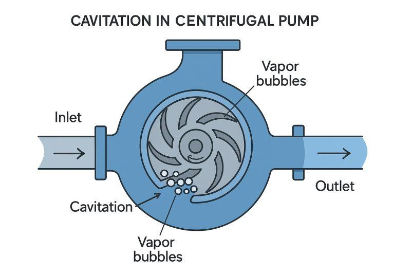
When cavitation occurs, where bubbles form and collapse inside the pump, a characteristic random high-frequency vibration is generated, which can cause changes in vibration values and FFT waveforms. While this change is a clue to suspect cavitation, you cannot "conclude it is cavitation based solely on vibration data." It is essential to make a comprehensive judgment by combining it with the confirmation of on-site abnormal noises (like "crackling" or "gravel passing through") and operating conditions such as suction/discharge pressure and flow rate.
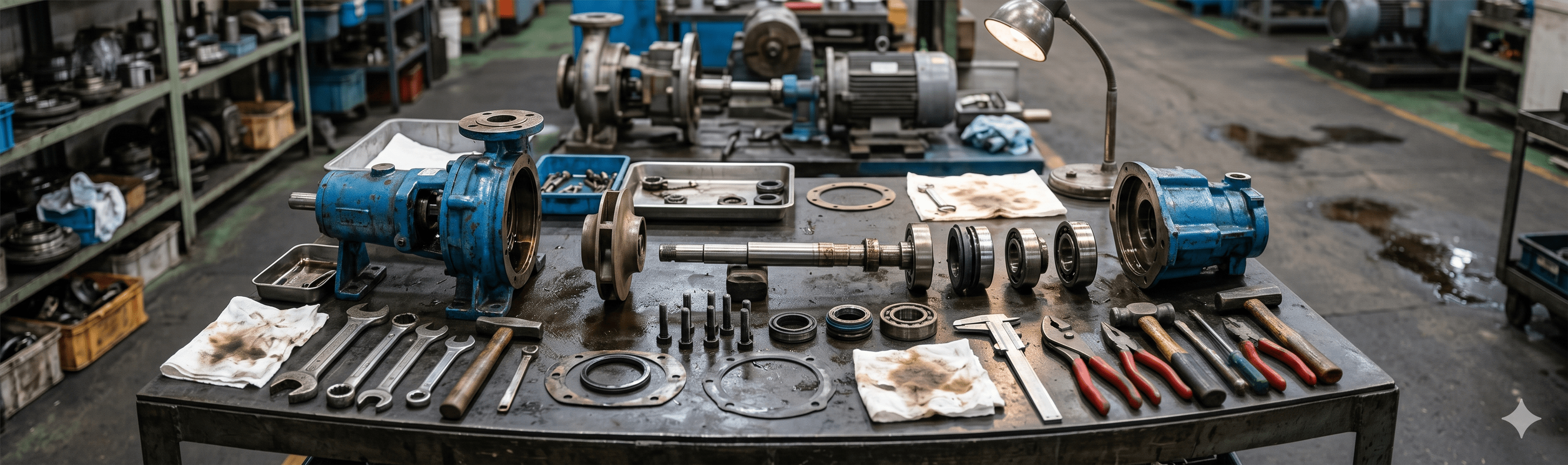
After confirming a change in vibration values or an abnormal waveform, perform a visual inspection on-site, check for abnormal noises and temperatures, and carry out overhaul inspections or repairs as necessary. The predictive maintenance cycle concludes when you measure the vibration again after the treatment and confirm that it has returned to the normal level.
For specific methods of setting thresholds (caution/warning levels) based on the normal state, please refer to "Centrifugal Pump Vibration Monitoring and Predictive Maintenance | Key Points of Threshold Setting and Trend Management". Furthermore, the specific process of actually detecting an abnormality and performing impeller cleaning or parts replacement is detailed in the repair case study "Specific Process of Centrifugal Pump Anomaly Detection, Overhaul Inspection, and Repair".
Centrifugal pump vibration diagnosis begins with installing the sensor in the appropriate position and direction and accumulating daily data. Please build a highly reliable equipment management system by using conanair to capture signs of abnormalities as data while combining them with on-site confirmations.
| Company Name | NSXe Co.Ltd - Nakayama Hydrothermal Industry Co., Ltd. |
|---|---|
| Head Office | 7686-10 Hirano-cho, Suzuka, Mie513-0835, Japan zip code 513-0835 |
| Phone | +81-90-2189-1398 |
| FAX | +81-59-379-4704 |
| Business Hours | 8:00~17:00 |
| Office Regular Holiday |
Saturday afternoons, Sundays and public holidays |
| URL | https://conanair.com/ |
| Company Name | NSXe Co.Ltd - Nakayama Hydrothermal Industry Co., Ltd. |
|---|---|
| Head Office | 7686-10 Hirano-cho, Suzuka, Mie513-0835, Japan zip code 513-0835 |
| TEL | +81-90-2189-1398 |
| FAX | +81-59-379-4704 |
| Business Hours | 8:00~17:00 |
| Office Regular Holiday |
Saturday afternoons, Sundays and public holidays |
| URL | https://conanair.com/ |