


 Is an "Expensive Sensor" Really Necessary for Bearing Anomaly Detection?




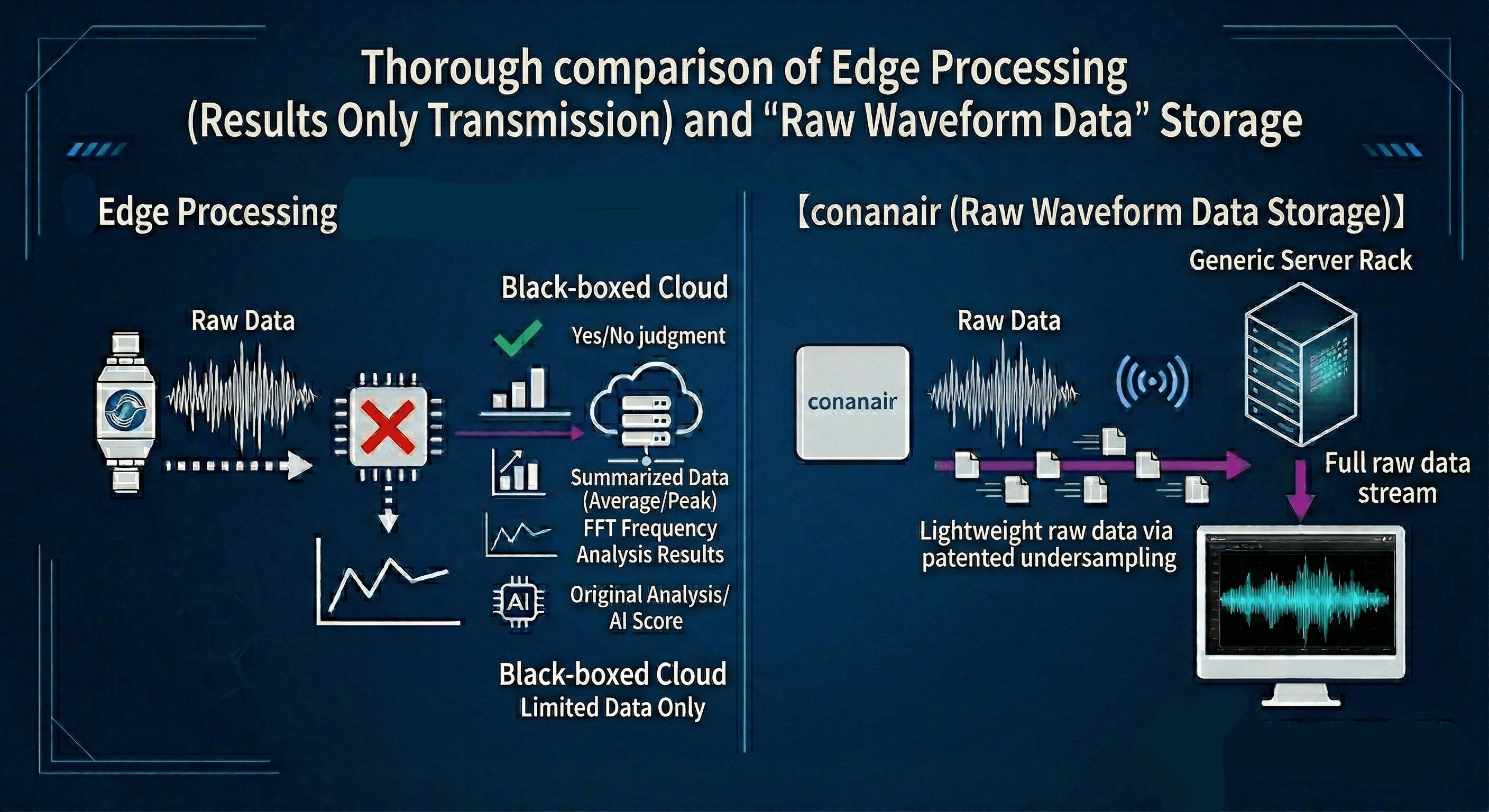
[Conclusion] As long as the "cycle" of the anomaly can be identified, expensive high-frequency sensors are unnecessary.
This article explains the basics of "Envelope FFT" (envelope processing) for bearing diagnosis and the difference with the patented "Undersampling" technology (Patent No. 6951474), which achieves overwhelming cost reduction by intentionally thinning out data, using intuitive diagrams that require no specialized knowledge.
In predictive maintenance of bearings, accurately reading "signs of anomalies" from vibration waveforms is crucial. Let's first look at what happens inside a bearing when damage occurs.
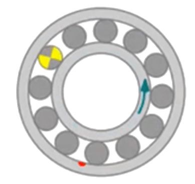
When damage such as scratches or flaking occurs on the inner or outer ring of a bearing, a "damped impact vibration" (a fine vibration that echoes like a tapping sound) in a high-frequency band of 2 to 8 kHz is generated every time a ball (rolling element) passes through the damaged part.
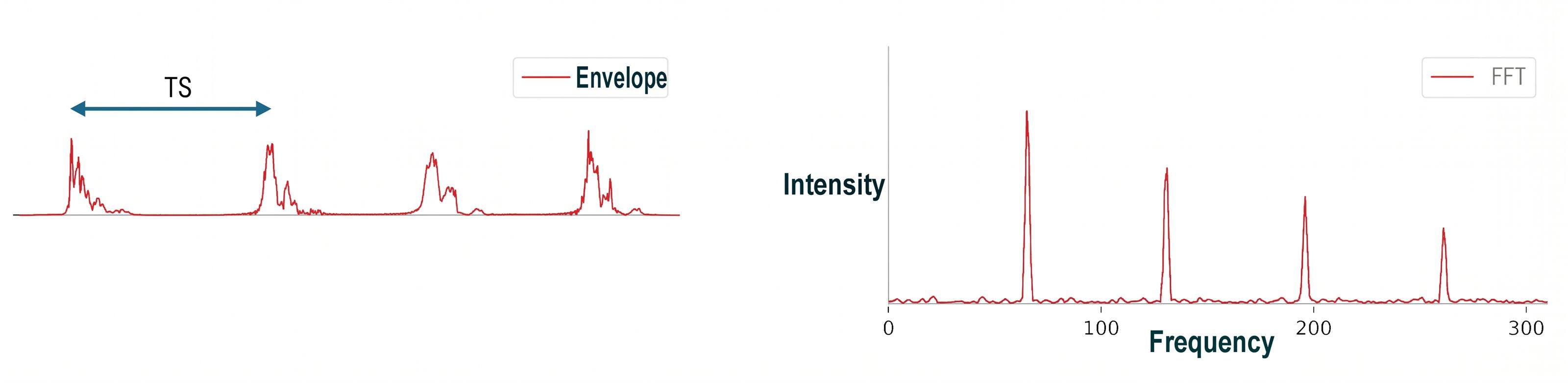
The interval at which these impact vibrations continuously occur is called "TS (characteristic cycle of bearing damage)." Since TS matches the pass frequency calculated from the bearing structure and rotation speed, if this "TS" can be found in the vibration data, the location of the bearing damage can be accurately identified.
You might think, "If we have raw vibration data, can't we just run a frequency analysis (FFT) to find the TS?" However, diagnosis is not possible with just that.

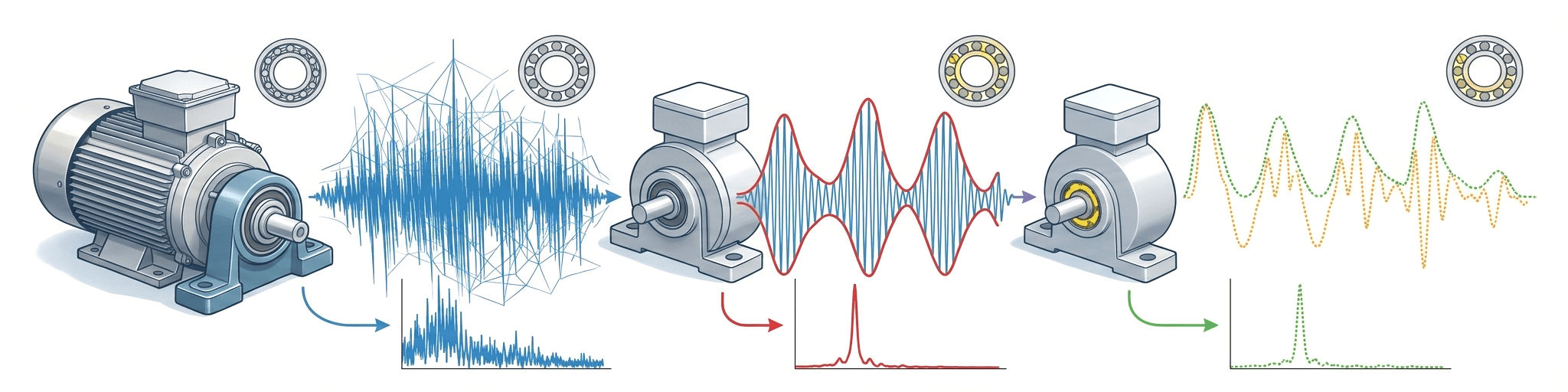
As shown in the figure above (right), even if the fine high-frequency raw waveform in blue is analyzed by FFT as is, the information is buried in the cluster of fine waveforms, and the essential "TS (characteristic cycle)" cannot be found.
This is where "Envelope processing" becomes necessary.
As shown in the figure above, only the outer cover (envelope: red line) is extracted by connecting the peaks of the jagged blue raw waveform.
By performing FFT analysis (Envelope FFT) on this red envelope waveform, the peak corresponding to TS appears clearly as a "sharp single peak" for the first time, making it possible to accurately identify bearing damage. This is the foundation of conventional precision diagnosis.
Conventional technology required an "expensive high-speed sampling sensor" to create a clean red envelope. However, conanair overturned this common sense with its patented "Undersampling" technology.
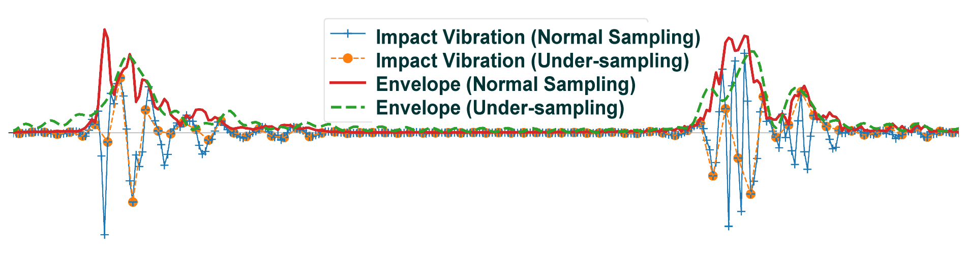
Undersampling is a technology that intentionally acquires (thins out) vibration data at a low sampling cycle.
When high-frequency vibrations are measured at a low cycle, the original waveform breaks down and is recorded as a different waveform called "aliasing noise" (the orange dotted line in the figure above).
Normally, this noise is avoided as a measurement error, but conanair actively utilizes it as a "sign that high-frequency abnormal vibrations are occurring."
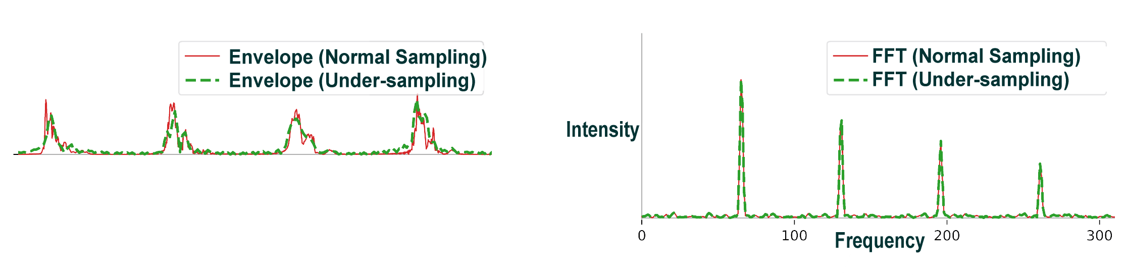
The waveform containing aliasing noise (orange dotted line) is not the correct waveform, but the most important information—the timing of the "cycle where the impact occurs (TS)"—is not lost.
By applying envelope processing and then an FFT to this thinned-out alias waveform, the bearing damage cycle (TS) can be identified exactly as when measured with conventional expensive equipment (the green dotted peak in the figure above).
Through this paradigm shift, conanair achieves high-precision bearing diagnosis with a general-purpose component configuration while minimizing data size to the absolute limit.
By focusing on the "cycle" of the anomaly rather than absolute numerical measurement, it realizes an optimal lightweight, low-cost, and high-precision system for on-site predictive maintenance.
Related Practical Guides and Technical Documents
For specific anomaly detection procedures in the field, please refer to the practical guide below.
 Bearing Anomaly Detection | Practical Application of Acceleration, Velocity RMS, and FFT Analysis
For detailed explanations of the patent, including technical limitations, please see the following page.
| Company Name | NSXe Co.Ltd - Nakayama Hydrothermal Industry Co., Ltd. |
|---|---|
| Head Office | 7686-10 Hirano-cho, Suzuka, Mie513-0835, Japan zip code 513-0835 |
| Phone | +81-90-2189-1398 |
| FAX | +81-59-379-4704 |
| Business Hours | 8:00~17:00 |
| Office Regular Holiday |
Saturday afternoons, Sundays and public holidays |
| URL | https://conanair.com/ |
| Company Name | NSXe Co.Ltd - Nakayama Hydrothermal Industry Co., Ltd. |
|---|---|
| Head Office | 7686-10 Hirano-cho, Suzuka, Mie513-0835, Japan zip code 513-0835 |
| TEL | +81-90-2189-1398 |
| FAX | +81-59-379-4704 |
| Business Hours | 8:00~17:00 |
| Office Regular Holiday |
Saturday afternoons, Sundays and public holidays |
| URL | https://conanair.com/ |